Wiegand Wave User Guide (v2.0)
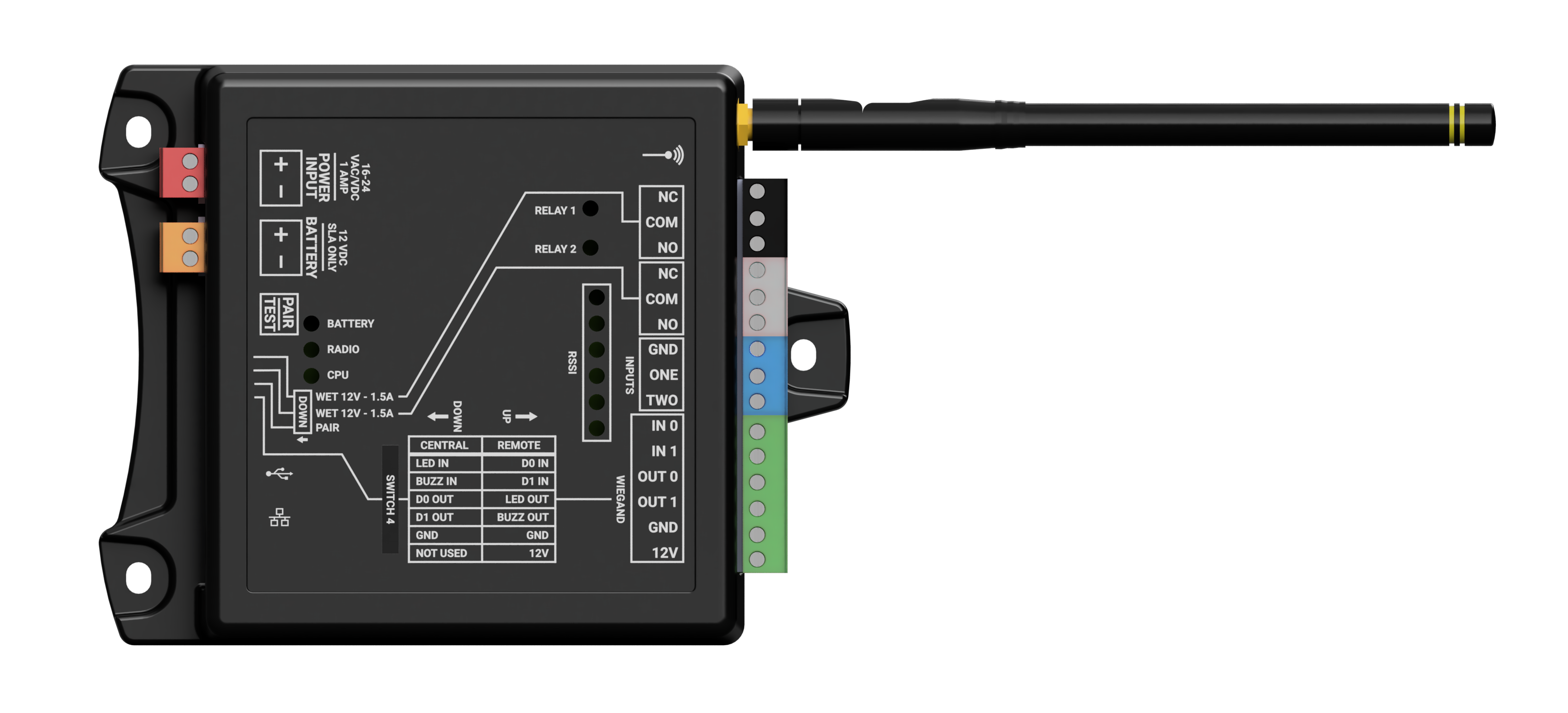
| Product Description | The Wiegand Wave is a wireless Wiegand bridge that transmits wireless signals (including Wiegand access codes and two contact inputs for controlling two relays) between remote Wiegand interface devices and a central access control module or panel. |
|
Operating Voltage |
16-24 VAC/VDC |
|
Operating Current |
64mA (idle), 159mA (transmit) |
|
Operating Power |
2.6 watt (peak) |
| Protocol | Wiegand (26-bit) |
| Relays | Two NO/NC relays (dry or 12VDC wet) |
| Inputs | Two contact-closure inputs to ground (triggering relays on the paired unit) |
Before You Begin
Ensure you have all required materials and recommended tools needed for a successful installation.
| Part / Tool | Description | Quantity |
| WW100 | These units function as a working pair. Installation and configuration can not be completed unless both units are available. | x2 |
| Antenna | Provided | x2 one per unit |
| ⅛ inch flathead screwdriver | Not included, but recommended. | x1 |
| Power Supply | 16-24 VAC/VDC, 2A | x2 one per unit |
Overview
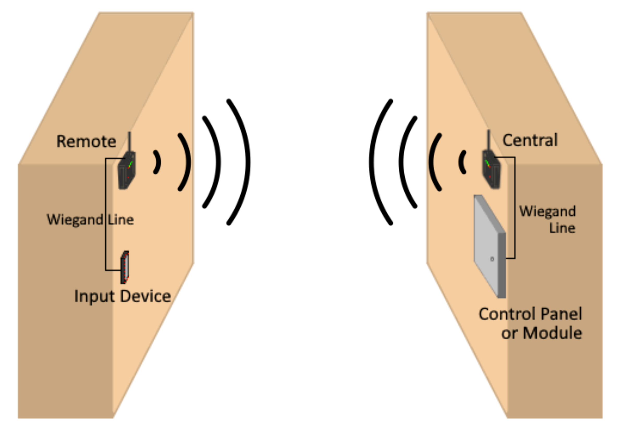
The Wiegand Wave transmits wireless signals (including Wiegand access codes and two contact inputs for controlling two relays) between remote Wiegand interface devices and a central access control module or panel. This allows the access system to operate as if hardwired without programming or user interaction.
Setup requires two Wiegand Wave units configured as “Central” and “Remote”.
Quick Start
Configure and pair units
- Screw on the included antenna, ensuring that it’s tight enough that it doesn’t fall or swing freely in any position. Complete this process on both units.
- Before mounting, connect both units to temporary power.
- Ensure all DIP switches are set to the up position.
- Press and hold the green Pair/Test button on both units for 10 seconds, or until the six RSSI LED indicators illuminate three times.
- Select one unit to be the Central unit , and one unit to be the Remote unit.
- Set DIP switch 4 down for the Central unit, up for the Remote unit.
- Set DIP switch 3 down to engage pairing mode on both units.
- Briefly press Pair/Test button on the Central unit to complete pairing.
- When all six RSSI LEDs light up, set DIP switch 3 up on both units.
- Disconnect from temporary power.
Mount and wire units
- Install each unit in a high, dry, unobstructed location.
⚠ The Wiegand Wave is NOT water resistant. - Connect 16-24VAC/VDC power to the red terminal block on each unit.
- Verify that the RSSI LEDs on both units illuminate every 30 seconds. This confirms successful pairing.
- Wire units based on their classification. Central: connect access panel to the green Wiegand terminal blocks. Remote: connect access readers to the green Wiegand terminal blocks.
Test connection (⚠ A green RSSI LED is required for reliable operation)
- Press Pair/Test and confirm blinking LEDs on both units.
- Test fob on access reader (when connected to a central access control panel) to ensure everything is working.
Mounting
Screw on the included antenna, ensuring that it’s tight enough that it doesn’t fall or swing freely in any position. Mount the unit in an area where the antenna has a mostly-unobstructed airway towards its paired unit, preferably high and near an exterior wall or window if mounted indoors. The unit will require power and a Wiegand connection.
⚠ The Wiegand Wave is NOT water resistant.


Wiring
Watch the video below or follow the detailed instructional lists for each WW100 unit.
Central unit wiring
- Red terminal block: Connect 16-24VAC/VDC to the red terminal block. When connected properly, the CPU power LED will illuminate.
- OPTIONAL: Orange terminal block: If installing a backup battery, connect the battery to the orange terminal block to provide backup power in the event of a power outage. ⚠ Use 12VDC sealed lead acid battery ONLY.
- Green terminal block: Connect the Access Control panel using the GND, OUT0 (D0), and OUT1 (D1) terminals on the green terminal block.
- OPTIONAL: Green terminal block: If applicable, also connect IN 0 and IN 1 for the reader LED and buzzer control.
- Black/gray terminal blocks: If applicable, connect relay 1 or 2 to a door position sensor or similar device on the access control panel. Can be configured for “wet” or “dry” operation. The Central relay outputs are wirelessly connected to the Remote relay inputs.
- Blue terminal block: Connect the door-open signal from the access control panel to input One or Two and GND, similar to how you would connect it to a door strike or gate controller relay. The Central relay inputs are wirelessly connected to the remote relay outputs.
Remote unit wiring
- Red terminal block: Connect 16-24VAC/VDC to the red terminal block. When connected properly, the CPU power LED will illuminate.
- OPTIONAL: Orange terminal block: If installing a backup battery, connect the battery to the orange terminal block to provide backup power in the event of a power outage. ⚠ Use 12VDC sealed lead acid battery ONLY.
- Green terminal block (Wiegand): Attach the reader to the 12V, GND, IN0 (D0), and IN1 (D1) terminals on the green terminal block. Unit should turn on once connected to 12V and GND.
- OPTIONAL: Green terminal block (Wiegand): Reader LED and buzzer control.
- Black/white terminal blocks: Connect devices like door strikes or gate controllers to either relay 1 or 2. Can be configured for “wet” or “dry” operation. The Remote relay outputs are wirelessly connected to the Central relay inputs.
- OPTIONAL: Blue terminal block: Optionally, connect a REX button or door sensor to inputs One and/or Two, and GND. The remote relay inputs are wirelessly connected to the Central relay outputs.
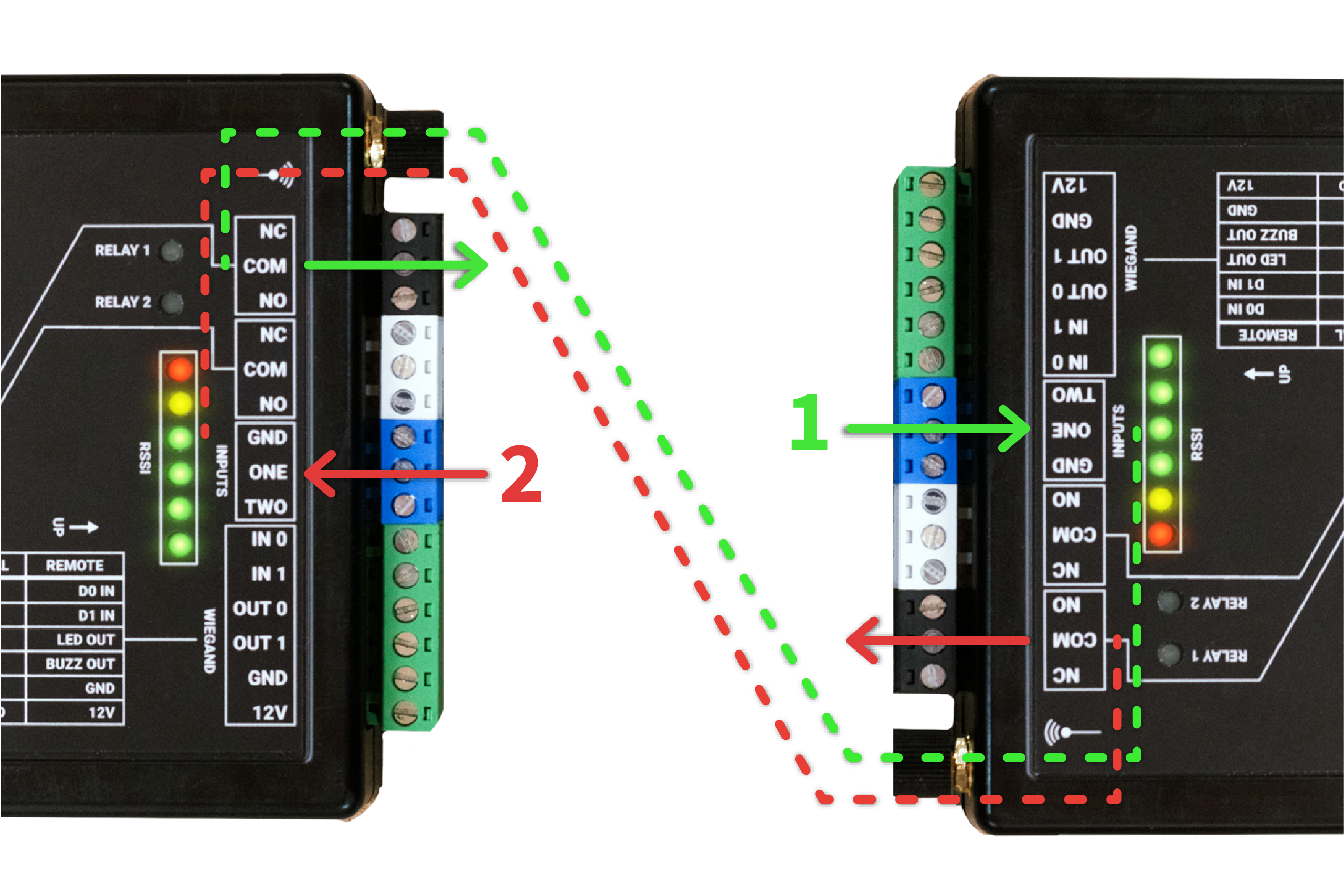
Central unit (left) and Remote unit (right)
The image above shows the interaction between the inputs and relays. A contact closure input on one unit will trigger the corresponding relay on the paired unit.
In this scenario, a door position input triggers the Input One on the Remote unit, shown in green. This wirelessly signals the Central unit’s Relay One to activate. This could be connected to a position sensor input on the access control module or panel for monitoring the state of the door. If a card scan is approved, the access control module or panel would respond with a contact closure to the Central Input One, shown in red. The Central unit then signals Relay One to activate on the Remote unit, which opens the door.
Configuration
The units are configured through the blue DIP switch block on the side of the unit near the orange battery terminals.
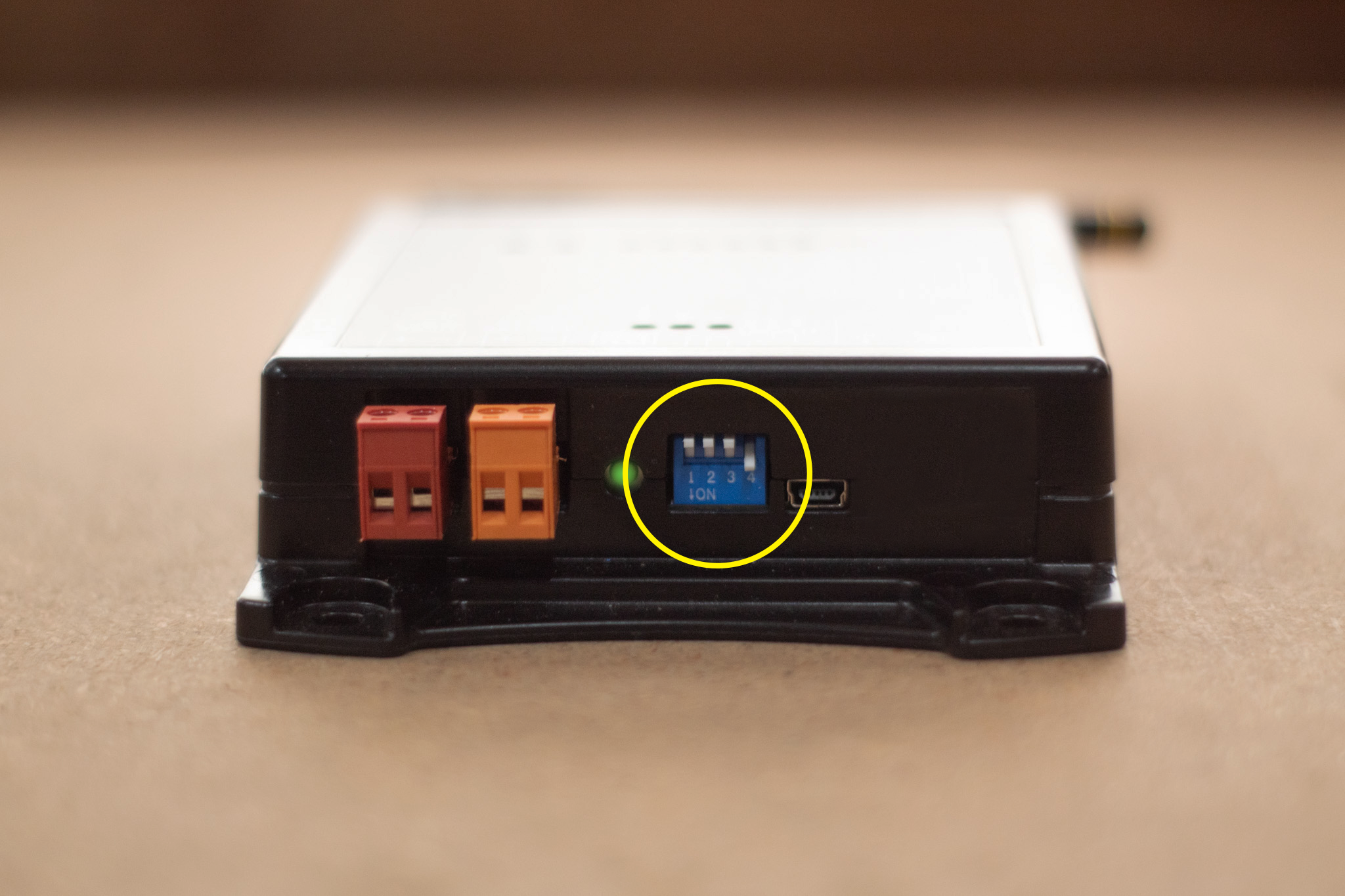
The switches allow you to configure the unit for Central or Remote operation, enable pairing mode, or set relays to be Wet or Dry. Dry relays act as simple switches that open or close a circuit without supplying power. Wet relays provide a 12VDC (1.5A Max) output to directly power devices when activated.
| SWITCH | UP | DOWN |
| Switch 1 (Relay 1) | Dry | Wet |
| Switch 2 (Relay 2) | Dry | Wet |
| Switch 3 (Pairing) | Normal mode | Pairing mode |
| Switch 4 (Role) | Remote | Central |
Pairing Units
Perform the following steps to pair the Central and Remote units. It’s recommended to have them in close proximity for pairing, but not required. Once successfully configured and paired, the units will communicate every 30 seconds. The RSSI LEDs will indicate signal strength between the two units.
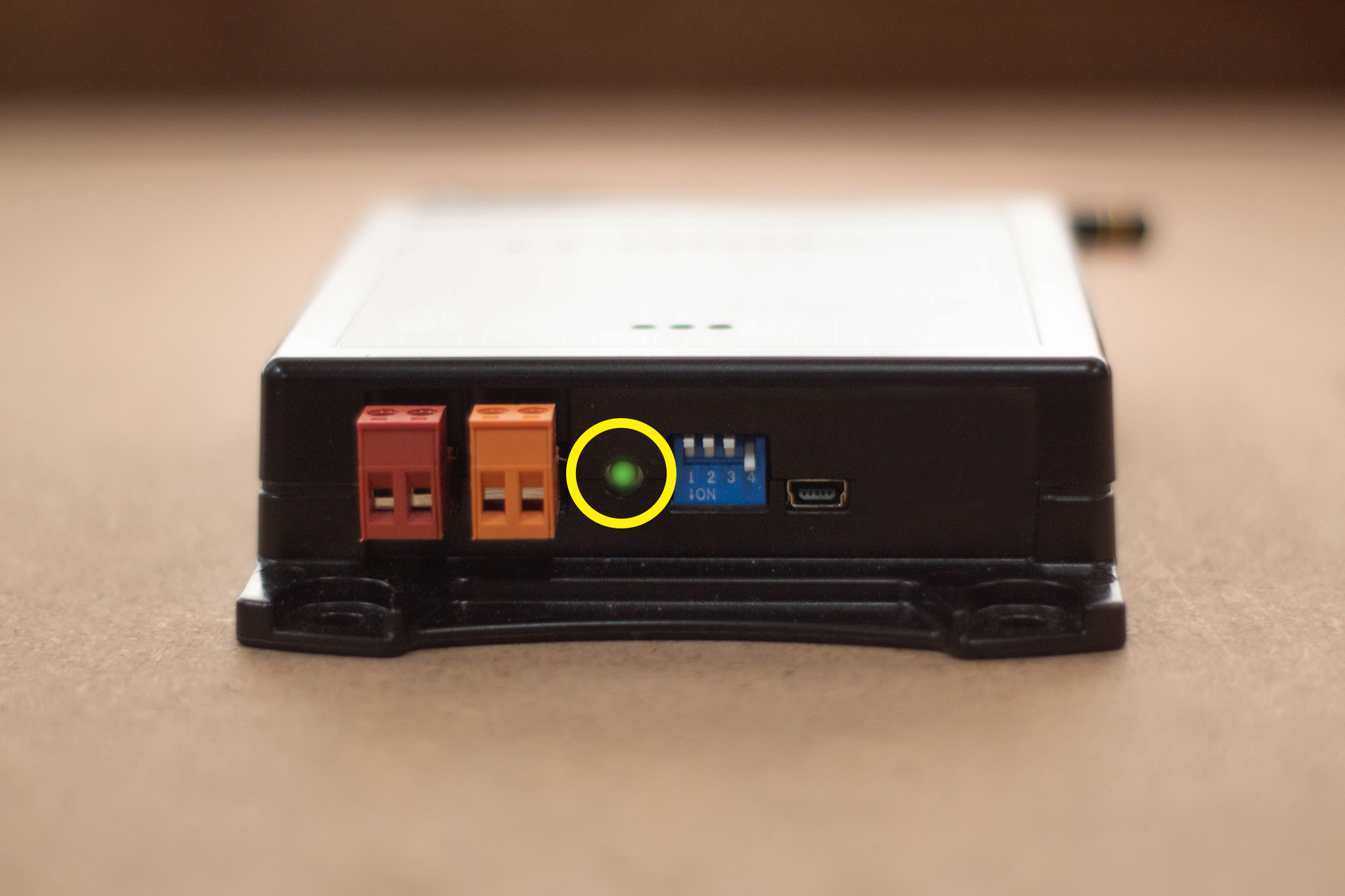
- Move all DIP switches to the up position on both units.
- Press and hold the green Pair/Test button on both units for 10 seconds, or until the six RSSI LED indicators illuminate three times.
- Set DIP switch 4 down on the Central unit
- Set DIP switch 4 up on the Remote unit.
- Move DIP switch 3 to the down (pairing mode) position on both units.
- Briefly press the green Pair/Test button on the Central unit. RSSI lights will count up until all six are lit on both units, indicating pairing is complete.
- Move DIP switch 3 back to the up (normal mode) position on both units.
Unpairing Units
In the event that you need to unpair two WW100’s from each other, perform the following steps to unpair the Central and Remote units. You do not need to have the units in close proximity to each other to complete this.
- Move all DIP switches to the up position on both units.
- Hold the green Pair/Test button until the LEDS on the top of the unit light up 3 times. This process takes roughly 10 seconds.
Testing
For a quick connection test, briefly press the green Pair/Test button. The RSSI LEDs on both units will strobe if successful.
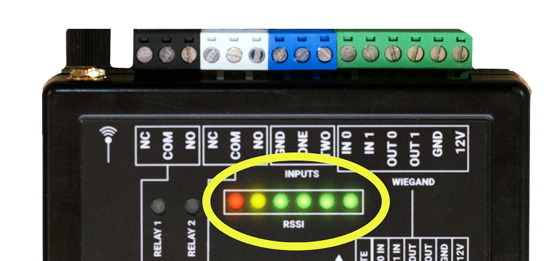
For further testing, connect a Weigand reader to the Remote unit, the reader should turn on during this test. Swipe a fob on the reader and look for the following:
- The RSSI lights should illuminate, indicating the signal strength.
- The Radio Power LED should illuminate briefly, indicating that a message was sent or received.
- The Central unit should output a Wiegand code that matches the fob swiped on the reader.
- If wired correctly to an access control panel, the Central unit will trigger the relay input and the corresponding relay output on the Remote unit will illuminate to indicate a successful door open.
Repeat this test with the devices mounted in their desired locations.
After mounting, check the signal strength on the RSSI LED indicators. You may want to adjust the mounting location and antenna orientation if the signal strength is poor or if the response is inconsistent.
⚠ A green RSSI LED is required for reliable operation
FCC Regulatory Statement
FCC ID:2BGQ6WW100: This device complies with part 15 of the FCC rules.
Operation is subject to the following two conditions: (1) This device may not cause harmful interference, and (2) this device must accept any interference received, including interference that may cause undesired operation.
⚠ IMPORTANT! Any changes or modifications not expressly approved by the party responsible for compliance could void the user’s authority to operate this equipment.
NOTE: This equipment has been tested and found to comply with the limits for a Class B digital device, pursuant to part 15 of the FCC Rules. These limits are designed to provide reasonable protection against harmful interference in a residential installation. This equipment generates, uses and can radiate radio frequency energy and, if not installed and used in accordance with the instructions, may cause harmful interference to radio communications. However, there is no guarantee that interference will not occur in a particular installation. If this equipment does cause harmful interference to radio or television reception, which can be determined by turning the equipment off and on, the user is encouraged to try to correct the interference by one or more of the following measures:
- Reorient or relocate the receiving antenna.
- Increase the separation between the equipment and receiver.
- Connect the equipment into an outlet on a circuit different from that to which the receiver is connected.
- Consult the dealer or an experienced radio/ TV technician for help.
FCC Radiation Exposure Statement
This equipment complies with FCC radiation exposure limits set forth for an uncontrolled environment. This equipment should be installed and operated with minimum distance 20cm between the radiator and your body.
This transmitter must not be co-located or operating in conjunction with any other antenna or transmitter. The antennas used for this transmitter must be installed to provide a separation distance of at least 20 cm from all persons and must not be co-located or operating in conjunction with any other antenna or transmitter.
FCC Caution
To assure continued compliance, any changes or modifications not expressly approved by the party responsible for compliance could void the user’s authority to operate this equipment. (Example – use only shielded interface cables when connecting to computer or peripheral devices).
