ONE TO MANY System Installation
System Overview
The KNECT™ One to Many system is a multipoint wireless bridge, capable of transmitting data using either Wiegand or OSDP, that can be remotely managed and monitored used the Aether RF IoT platform.

FeaturesCloud Connected: Optionally register the device on Aether RF IoT to unlock advanced reporting and diagnostic features. Range: Aether RF’s proprietary radio technology transmits reliable signal up to a mile through obstructions, and up to 25 miles line of sight. Operation: Supports up to 8 KNECT™ Endpoints per Gateway, and 2 KNECT™ Gateways per system. |
BenefitsExpanded coverage: Transmitt data to up to eight remote access points using Aether RF’s proprietary radio technology, all from one powerful source. Less hardware: Reduces the amount of devices required on site compared to traditional point to point wireless bridges. Convenient size: Designed to accommodate a wide variety of site specifications, each device |
DEVICES
The KNECT One to Many System is composed of several critical pieces of equipment; KNECT Gateways, an ARF Tether, and multiple KNECT Endpoints. Each device has a minimum and maximum quantity that a single One to Many System can support.

Before You Begin
The following equipment is necessary to perform basic system installation and should be included in your kit.
- 1) ARF Tether with compatible transformer
- (1) KNECT Gateway
- (2) KNECT Endpoints with compatible transformers
Depending on the specifications of your installation, additional hardware may be required to complete the system setup. This hardware will need to be purchased separately.
One additional Gateway (KGW-100) and up to six additional Endpoints (KEP-200) can be used if your installation covers additional access points. However, the One to Many system will not support more than two Gateways and will never require more than one Tether.
Additionally, If your installation requires OSDP, you will need to purchase and install an OSDP add-on for the Gateway.
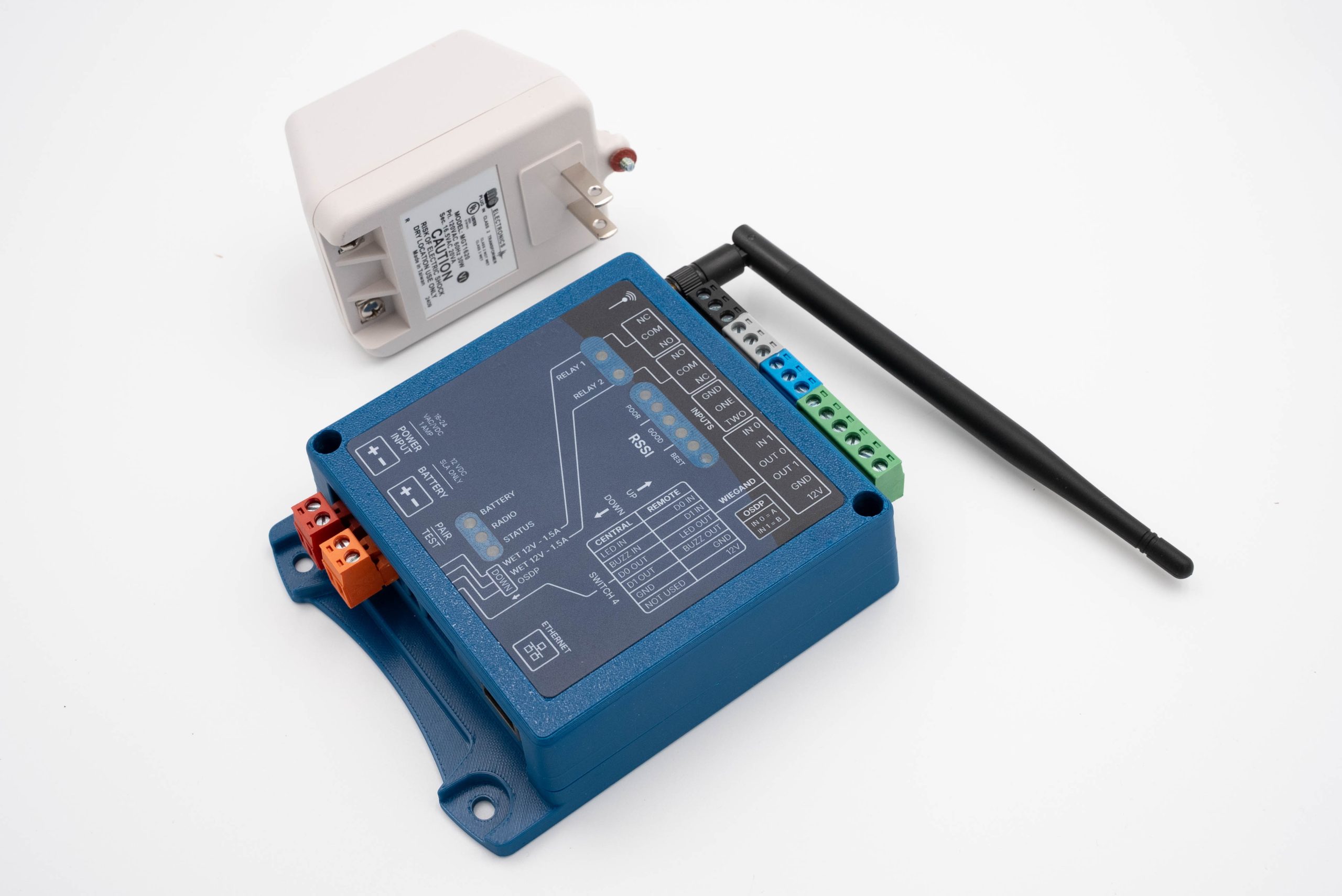
KEP-200 Single
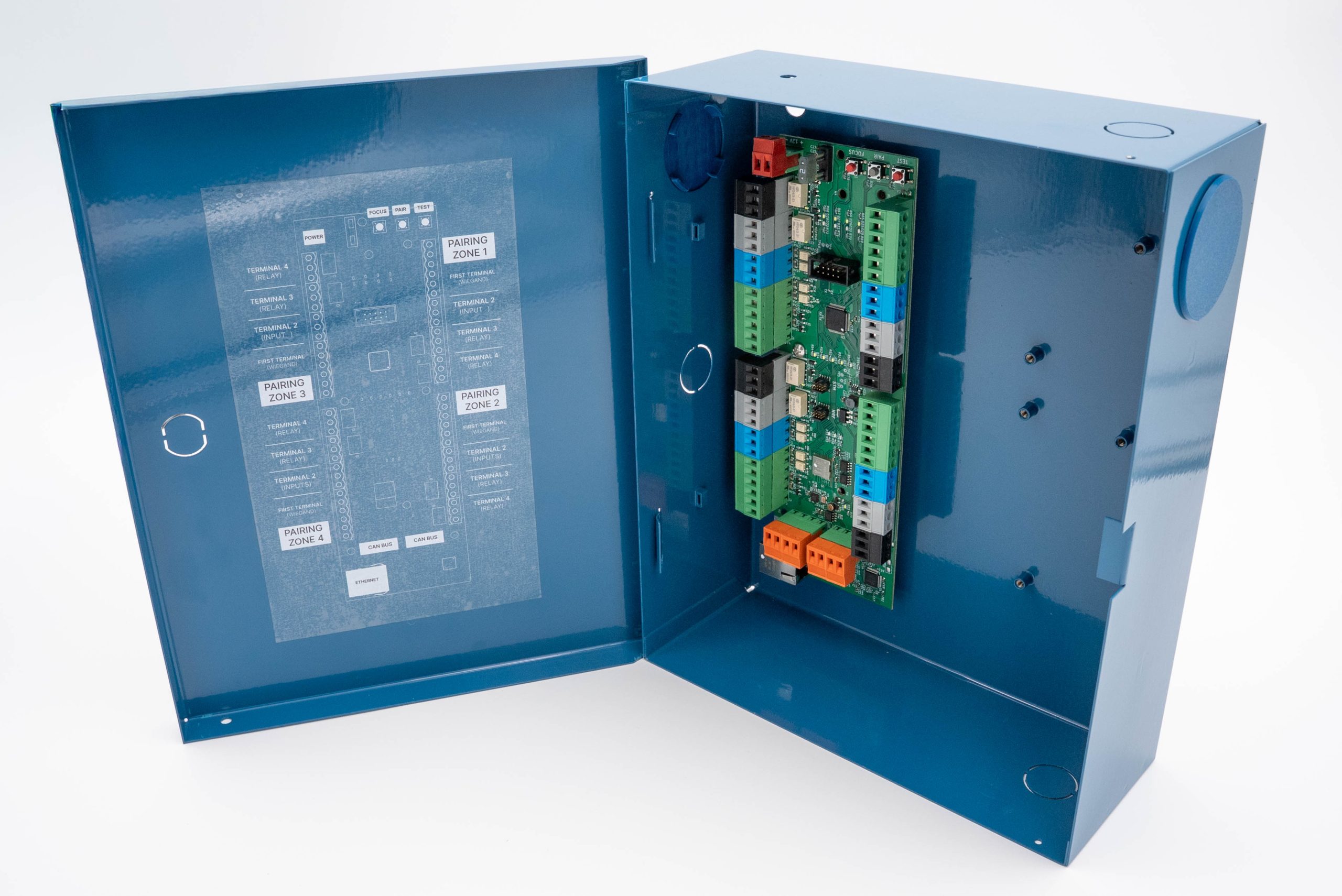
KGW-100
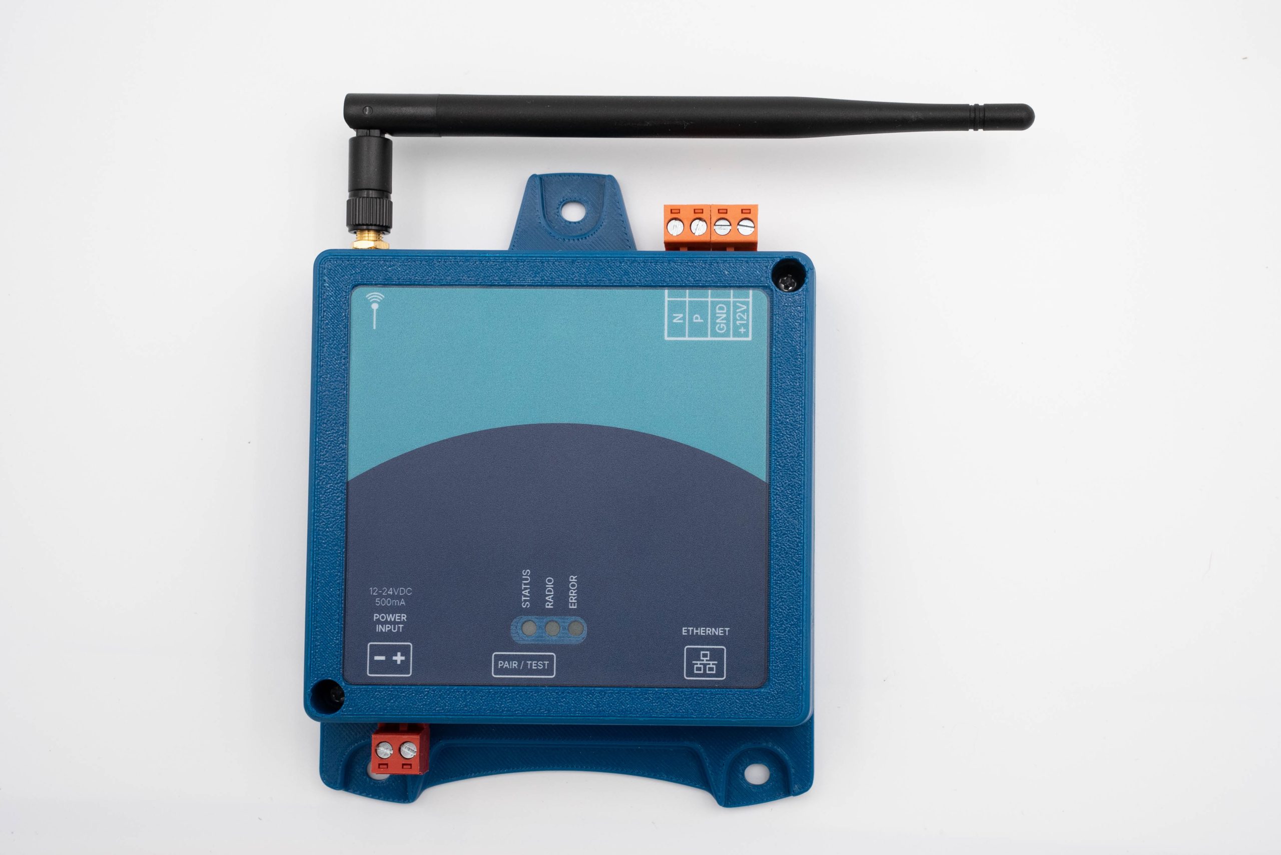
ARF-T100
MOUNTING CONSIDERATIONS PER DEVICE
Gateway
Mount the Gateway in a secure dry place, near the site’s primary access control panel. Do not mount the device in areas that may be susceptible to damage due to tampering or the elements.
⚠ The KNECT Gateway is NOT water resistant. ⚠
Tether
Mount the Tether in a location that provides the best signal support from the Gateway to the various Endpoints on site. This location should be an area where the antenna has a mostly-unobstructed airway, preferably high and near an exterior wall or window if mounted indoors. You will want to note the location of the Tether for future service calls.
⚠ The ARF Tether is NOT water resistant. ⚠
Endpoints
Before mounting, ensure the antenna is tight enough and doesn’t fall or swing freely in any position. Mount the unit in an area where the antenna has a mostly-unobstructed airway, preferably high and near an exterior wall or window if mounted indoors.
⚠ The KNECT Endpoint is NOT water resistant. ⚠
SYSYEM DESIGN AND CONFIGURATION
The One to Many System has 3 key components. It is recommended that each component be installed in the following order.
- Mount, Power, and Wire the Gateway (KGW-100)
- Wire, mount, and Configure the Tether (ARF-T100)
- Power, Pair, and Mount each Endpoint (KEP-200)
KEP-200 Single
KGW-100
ARF-T100
STEP 1: Mount, Power, and Wire the Gateway
1. Mount the Gateway according to the mounting specifications.
2. Power the Gateway by connecting 12-24V DC power to the RED terminal block on each Gateway.

3. If you are connecting multiple Gateways, you’ll need to wire the Gateways together through the orange CAN bus.

4. Connecting Gateways to Ethernet. If you intend to utilize the cloud-based monitoring features of the One to Many system, you will need to wire the Gateway an Ethernet connection. Ethernet is also required in the event firmware updates are necessary
5. Connecting Gateways to a Control Panel. Each Gateway has four pairing zones that will need to be connected to the corresponding data points for each access point (DOOR) on the access control panel.

Gateway Wiring Per Pairing Zone
- GREEN TERMINAL: Wires into 12V, Ground, Data 1, Data 0, LED (IN 1), Buzzer Control (IN 0)
- BLUE TERMINAL: Input 2, Input 1, Ground
- WHITE TERMINAL: Normally Open, COM, Normally Closed
- BLACK TERMINAL: Normally Open, COM, Normally Closed

STEP 2: Mount, Wire, and Configure the Tether
1. Mount the Tether according to the mounting specifications.
2. Connect the Tether to the Gateway using the CAN bus to power. Optionally, connect 12-24V DC power to the red terminal block.
3. The Tether will automatically connect and configure. You’ll know the Tether is properly connected when the Status LED on the Tether turns on along with the corresponding LED on the Gateway.

STEP 3: Pair, Wire, and Mount each Endpoint
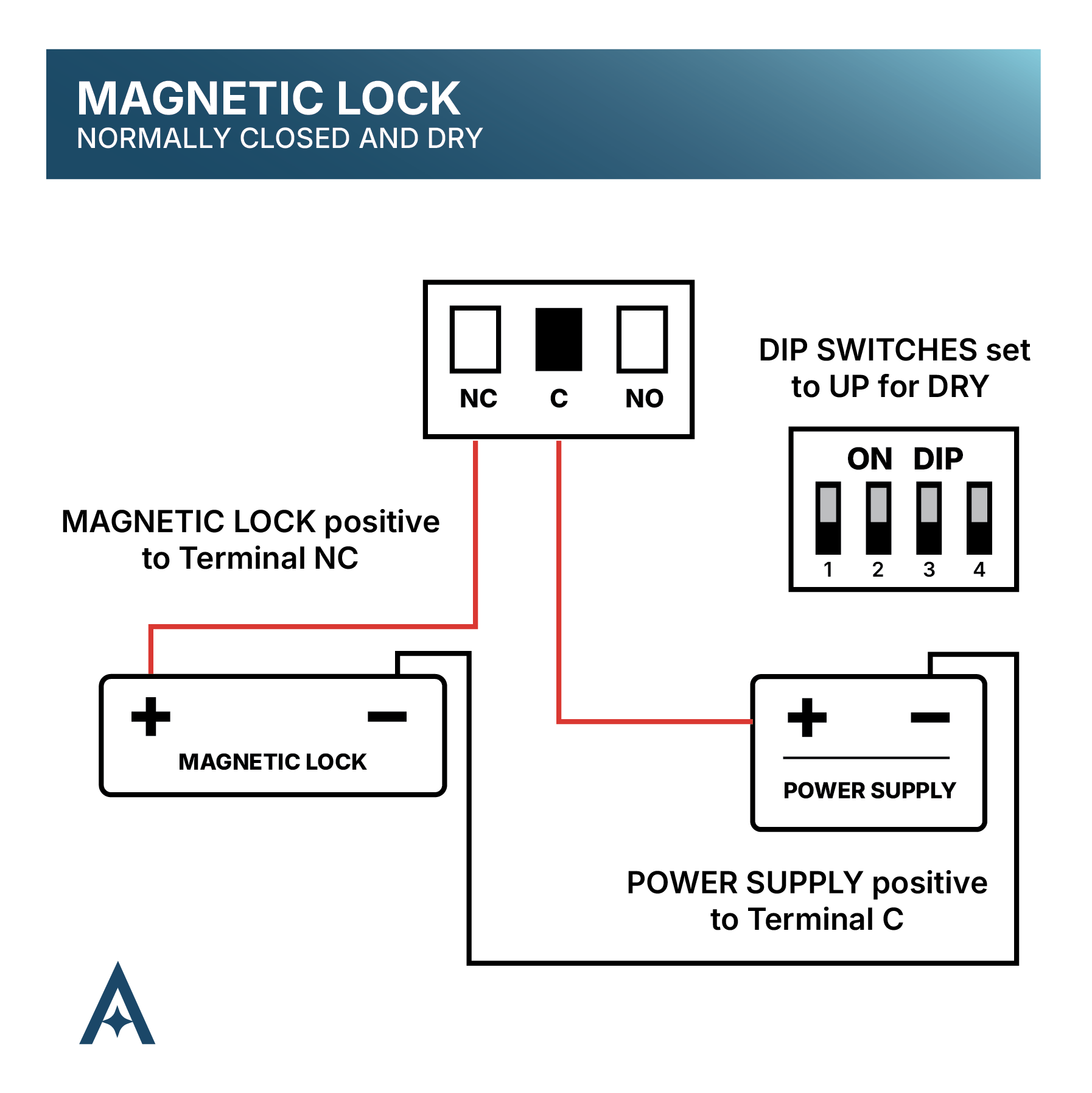
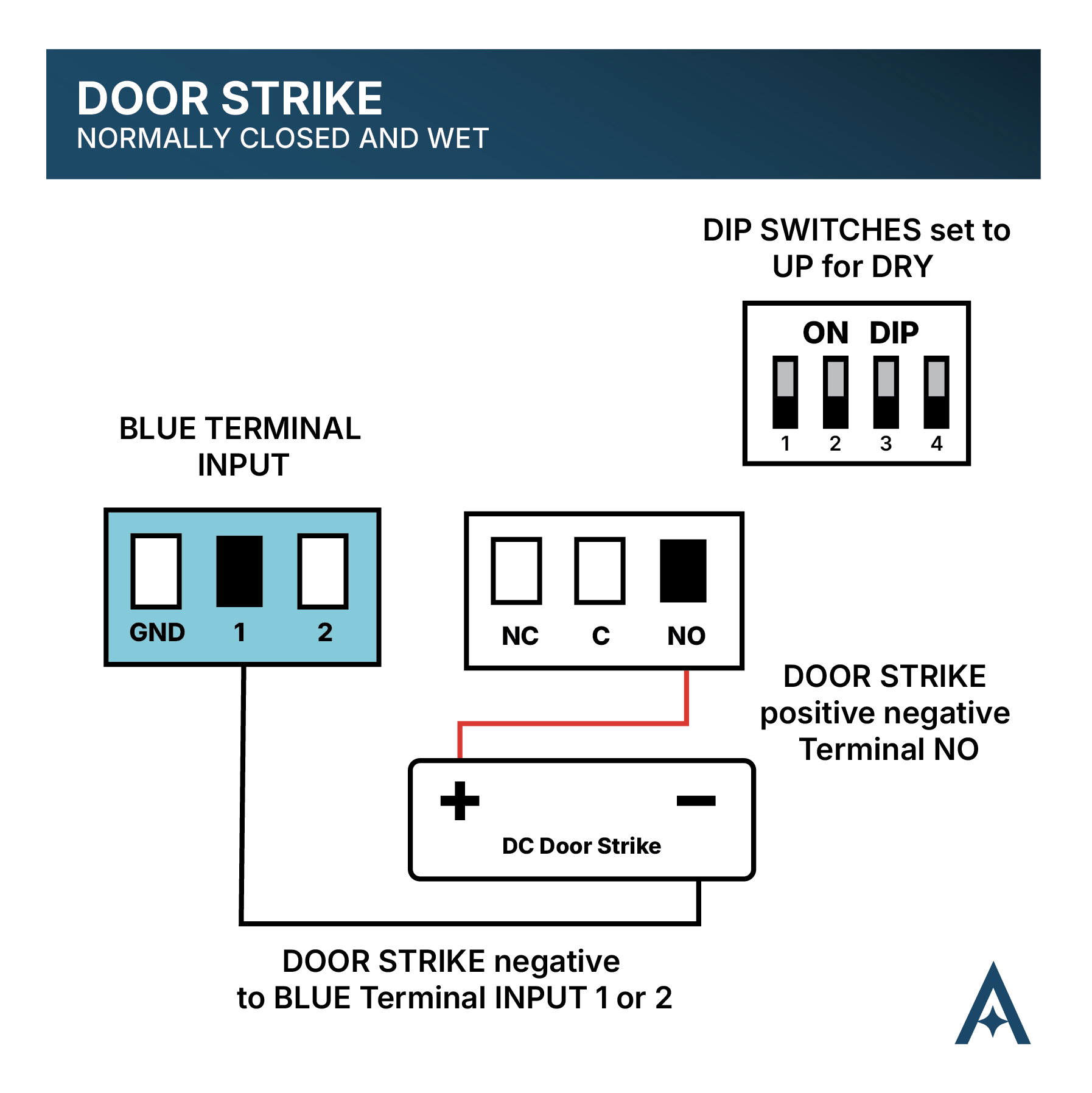
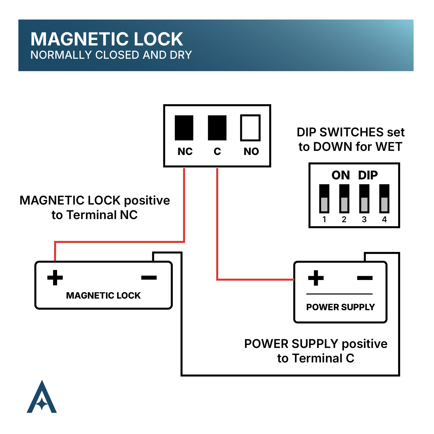
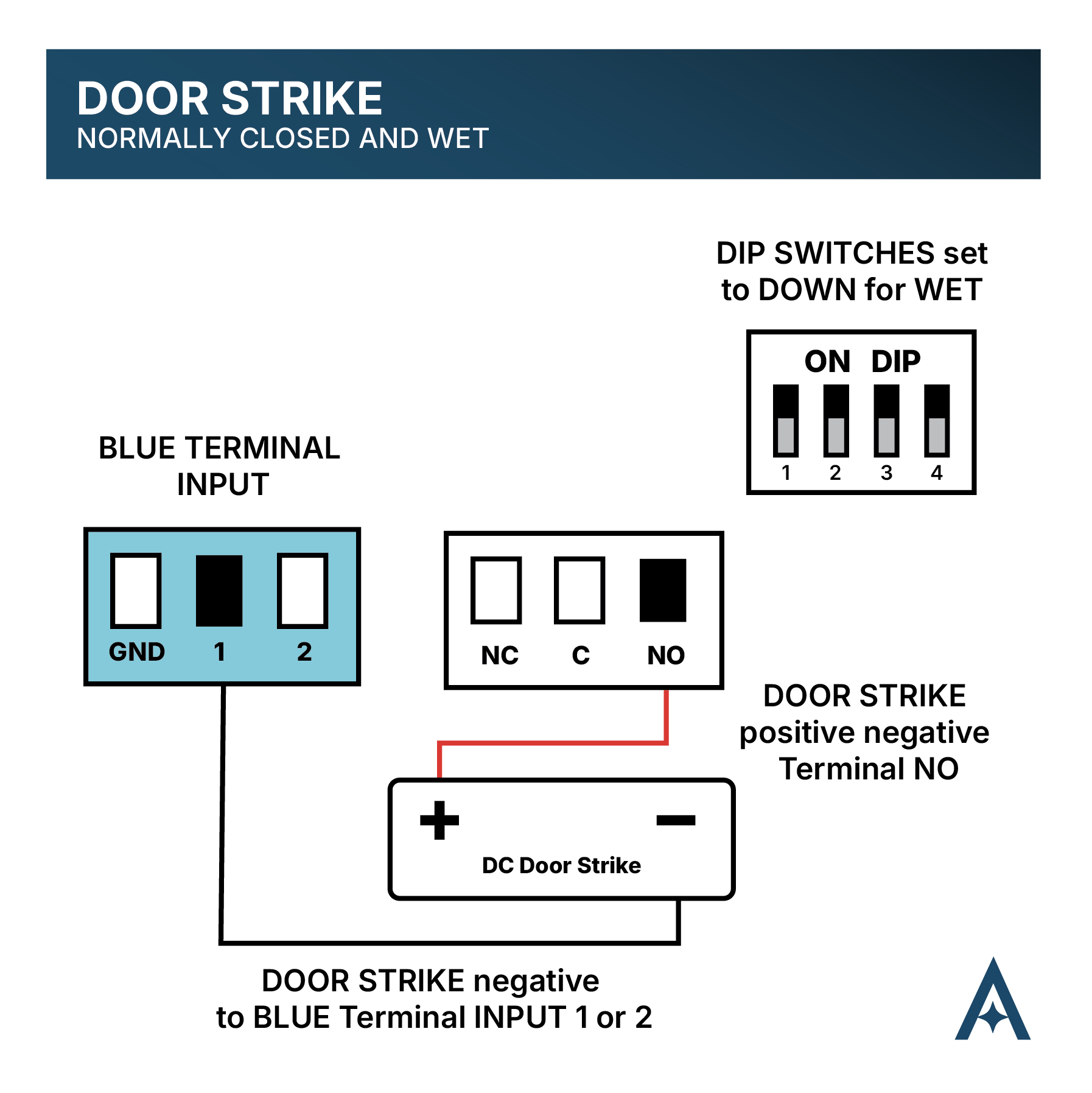
1. Set the DIP Switches on each Endpoint according to your site specifications, determining wherther contacts will be either WET or DRY.
NOTE: The fourth DIP Switch will always be set to UP in a One to Many installation, as the Gateway will act as the Central Unit for all Endpoints.

2. Begin pairing Endpoints to the Gateway. Each Gateway can host up to four Endpoints. If you have more than four Endpoints, you’ll need to repeat this process for each Gateway.
You do not need to adjust any setting on the Endpoint during pairing, each Endpoint will enter Pairing Mode once powered.
- Connect 16-24VAC/VDC power to the Red terminal block on the first Endpoint you wish to pair. Do not power on more than one Endpoint at a time. This will disrupt the pairing process.
- Locate the FOCUS button on the Gateway. This will be used to select a pairing zone for the Endpoint. You may only have 1 Endpoint assigned per zone.
- Press and release the FOCUS button to select your pairing zone. The LEDS of each quadrant will flash to indicate which zone you are currently in.
- The Gateway will search for the available Endpoint and connect automatically. This process must be done individually. It is important you do not have more than one endpoint in Pairing Mode during this step.
- Locate and Press the PAIR button on the Gateway to confirm pairing the Endpoint to your selected zone.
- LEDs on the Endpoint will flash repeatedly to indicate pairing is in process, when the lights turn off pairing is complete.
- Press the TEST button on the Gateway to initiate a test transmission to the Endpoint. Flashing RSSI lights on the Gateway will show the signal strength and confirm proper pairing.
- Press the FOCUS button on the Gateway to cycle to your next pairing zone.
- Complete the same process (steps 2-8) for each additional Endpoint in your system.
If using more than four Endpoints, complete these steps on the second Gateway for Endpoints 5-8, treating them as if they were an original 1-4).
3. Begin connecting Endpoints to each access point. (Door strike, Maglock, REX button, etc.). Each Endpoint in the One to Many system will follow the same wiring specifications.
GREEN TERMINAL (Wiegand terminal): Wires into 12V, Ground, Data 1, Data 0, LED, Buzzer Control
BLUE TERMINAL (Inputs): Input 2, Input 1, Ground
WHITE TERMINAL: Normally Open, COM, Normally Closed
BLACK TERMINAL: Normally Open, COM, Normally Closed
ORANGE TERMINAL: Wires into optional battery backup, Use 12VDC sealed lead acid battery ONLY.

4. Mount each Endpoint according to the following mounting specifications.
- Before mounting, ensure the antenna is tight enough and doesn’t fall or swing freely in any position.
- Mount the unit in an area where the antenna has a mostly-unobstructed airway, preferably
WIRING SCENARIOS
FUNCTIONAL TESTING
Setup is complete when pressing the Test/Pair button on the Endpoint causes the RSSI indicator to light up, confirming that a test packet was successfully sent to and received from the Gateway.
Alternatively, select a paired zone and press the Test/Pair button. This sends a packet to the Endpoint associated with that zone. The RSSI indicator should light up, confirming successful communication with the device.
RSSI & OTHER LED’S
Each device has various LEDs to signal specific operating states, or performance insights. Understanding the main LED behaviors will improve both installation and troubleshooting

UNPAIRING AND FACTORY RESET
Remove Endpoint from a Gateway
1. Use the FOCUS button on the Gateway to select the appropriate zone for the Endpoint you’re wanting to unpair.
2. Press and hold the Pair/Test button on the Endpoint for 10 seconds. Flashing LEDs will signal the device has been successfully unpaired from the system.
Remove Tether from a Gateway
Hold the Pair/Test button on the Tether for 10 seconds. Three simultaneously shining LED lights will indicate the device has been unpaired from the system.
CLOUD CONNECTED
It is recommended that the One to Many system be onboarded into the Aether RF IoT cloud platform in order to obtain detailed insights on device performance. Device registration should occur once your primary device is connected to ethernet.
If your organization is not already registered, it is recommended you do so prior to installation by visiting: AetherRFiot.com/register/dealer
FCC Regulatory Statement
FCC ID:2BGQ6WW100: This device complies with part 15 of the FCC rules.
Operation is subject to the following two conditions: (1) This device may not cause harmful interference, and (2) this device must accept any interference received, including interference that may cause undesired operation.
⚠ IMPORTANT! Any changes or modifications not expressly approved by the party responsible for compliance could void the user’s authority to operate this equipment.
NOTE: This equipment has been tested and found to comply with the limits for a Class B digital device, pursuant to part 15 of the FCC Rules. These limits are designed to provide reasonable protection against harmful interference in a residential installation. This equipment generates, uses and can radiate radio frequency energy and, if not installed and used in accordance with the instructions, may cause harmful interference to radio communications. However, there is no guarantee that interference will not occur in a particular installation. If this equipment does cause harmful interference to radio or television reception, which can be determined by turning the equipment off and on, the user is encouraged to try to correct the interference by one or more of the following measures:
- Reorient or relocate the receiving antenna.
- Increase the separation between the equipment and receiver.
- Connect the equipment into an outlet on a circuit different from that to which the receiver is connected.
- Consult the dealer or an experienced radio/ TV technician for help.
FCC Radiation Exposure Statement
This equipment complies with FCC radiation exposure limits set forth for an uncontrolled environment. This equipment should be installed and operated with minimum distance 20cm between the radiator and your body.
This transmitter must not be co-located or operating in conjunction with any other antenna or transmitter. The antennas used for this transmitter must be installed to provide a separation distance of at least 20 cm from all persons and must not be co-located or operating in conjunction with any other antenna or transmitter.
FCC Caution
To assure continued compliance, any changes or modifications not expressly approved by the party responsible for compliance could void the user’s authority to operate this equipment. (Example – use only shielded interface cables when connecting to computer or peripheral devices).