
One to Many installation guide
A KNECT Gateway at your access control panel, an ARF Tether carrying its radio, and a KNECT Endpoint at every door or gate. This guide covers mounting, wiring, pairing each door or gate to a zone, and testing.
What you're installing
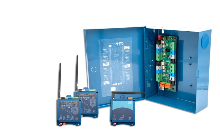
- KNECT Gateway KGW-100One, at the access control panel. This is the unit your panel sees.
- ARF Tether ARF-T100One, on a cable from the Gateway. This is the Gateway's radio.
- KNECT Endpoint KEP-200One at every door or gate, up to four per Gateway.
What you need before you start
In the One to Many Kit
- One KNECT Gateway (KGW-100)
- One ARF Tether (ARF-T100)
- Two KNECT Endpoints (KEP-200), each with its antenna
- Transformers for the units
You supply
- A small flat screwdriver for the terminal blocks
- One more KEP-200 for each door or gate past the two in the kit, up to four per Gateway
- A KGW-H OSDP hat for the Gateway, if the panel is running OSDP
- An enclosure for any unit going outdoors
- A 12V sealed lead acid battery at any Endpoint you want backed up
What each part does
Read this before you mount anything. The part that catches people is that the Gateway is not the radio.
The Gateway has no radio. The Tether is the radio.
The Gateway is the piece that talks to your access control panel. It does not transmit. The ARF Tether is what reaches the Endpoints, and it hangs off the Gateway on a cable so you can put the antenna somewhere with a view of the property while the Gateway stays in the equipment room.
| Part | Where it goes | What it connects to |
|---|---|---|
| KNECT GatewayKGW-100 | At the access control panel, indoors | The panel's reader inputs, and the Tether |
| ARF TetherARF-T100 | Wherever the signal is best, on a cable from the Gateway | The Gateway, over the CAN bus, which also powers it |
| KNECT EndpointKEP-200 | One at each door or gate | The reader, and the lock or gate operator |
The order to work in
Work from the panel outwards. Each stage depends on the one before it, and the Endpoints pair to a Gateway that has to be up and transmitting first.
- 1Mount, power and wire the Gateway At the panel. This is the unit your access control system sees.
- 2Mount, wire and configure the Tether Run it out to wherever it has the best view of the doors and gates.
- 3Pair, wire and mount each Endpoint One door or gate at a time. Pair it at the Gateway before you carry it out to the door.
Mounting
The Tether decides how this system performs. It is the only transmitting part at the panel end, so put it where it can see the doors and gates rather than wherever the cable happens to reach.
- Screw every antenna down tight before the unit goes on the wall, and point it straight up. An antenna that swings will drop the link intermittently, which is much harder to diagnose than one that never worked.
- Mount the Endpoints high, with as clear a path back to the Tether as the property allows.
- Keep at least 20cm between any antenna and a person. This is an FCC separation requirement.
None of the three are water resistant
Gateway, Tether and Endpoint all need an enclosure you supply if they are going outdoors.
Keep the antenna outside the enclosure, because a metal box around it will confine the signal.
Power
Every Endpoint takes its own power at its own door or gate. Nothing is powered over the radio link.
| Device | Input | Block |
|---|---|---|
| Gateway | 12 to 24 VDC | Red |
| Tether | Powered by the Gateway over the CAN bus. It can take its own 12 to 24 VDC instead. | Orange, for the CAN bus |
| Endpoint | 15 to 24 VAC or VDC | Red |
Wiring
The terminal blocks are color coded and the colors mean the same thing on both devices. What changes is what you land on them.
Gateway
At the panel.
| Block | Terminals | Goes to |
|---|---|---|
| Red | Power in | 12 to 24 VDC |
| Orange | CAN bus | The Tether, and a second Gateway if you have one |
| Green | 12V, Ground, Data 1, Data 0, LED (IN 1), Buzzer control (IN 0) | The panel's reader inputs |
| Blue | Input 2, Input 1, Ground | Contacts you want reported back to the panel |
| White | Normally closed, COM, Normally open | Auxiliary relay |
| Black | Normally closed, COM, Normally open | Relay |
Endpoint
At each door or gate. DIP switch 4 up on every one of them.
| Block | Terminals | Goes to |
|---|---|---|
| Red | Power in | 15 to 24 VAC or VDC |
| Orange | Battery | Optional 12V sealed lead acid, and nothing else |
| Green | 12V, Ground, Data 1, Data 0, LED, Buzzer control | The reader |
| Blue | Input 2, Input 1, Ground | Request to exit button, or a door contact |
| White | Normally closed, COM, Normally open | Auxiliary relay |
| Black | Normally closed, COM, Normally open | The lock, strike or gate operator |
If the panel runs OSDP
The Gateway needs a KGW-H OSDP hat fitted. The Endpoints do not, because OSDP is built into them.
DIP switch settings
The switch bank is printed on the face of each Endpoint. In a One to Many system the Gateway is the Central unit, so every Endpoint is a Remote.
| Switch | Position | Why |
|---|---|---|
| 4, unit role | UP on every Endpoint | Up is Remote. The Gateway is acting as the Central unit for the whole system. |
The remaining switches set each relay for a wet or a dry contact, to match how the lock is powered. Set them against the legend printed beside the bank on the unit in front of you, because the numbering is not the same across every KNECT product.
Pairing each door or gate to a zone
The Gateway holds four pairing zones, one per door or gate. You fill them one at a time, and the trick is to power up only the Endpoint you are pairing, so the Gateway has exactly one unit to find.
- 1Power one Endpoint, and only one 15 to 24 VAC or VDC into its red block. Leave the others unpowered until it is their turn.
- 2Press FOCUS on the Gateway to pick a zone The LEDs flash to show which zone you are on. Each press moves to the next one.
- 3Let the Gateway find the Endpoint It searches on its own and connects to the powered unit. This is why only one is on.
- 4Press PAIR to confirm The Endpoint's LEDs flash repeatedly while it pairs. When they go out, that zone is done.
- 5Press TEST to check it The RSSI lights flash back the signal strength for that zone. Do this now, while the Endpoint is still in your hand and its antenna can still be moved.
- 6Press FOCUS to move on Power the next Endpoint and run the same four steps against the next zone.
Testing the link
Press TEST on the Gateway and the paired Endpoint for that zone answers with its signal strength on the RSSI lights. The unit you pressed beeps when the test packet gets through.
Walk every zone before you close up any enclosures. Adding doors and gates does not shorten the range, because each Endpoint talks to the Tether directly rather than relaying through another Endpoint, so a weak zone is a placement problem at that one door or gate and not a symptom of the system being full.
Reading the RSSI lights
| Lights | Signal |
|---|---|
| 1 to 2 | Poor. An occasional 1 or 2 is fine, but a steady 1 or 2 is not a stable link. Review where the units and antennas are placed. |
| 3 to 4 | Good. |
| 5 or more | Best. |
More than four doors and gates
One Gateway holds four zones. For a fifth door or gate you add a second Gateway, chained to the first over the orange CAN bus block, and pair its zones the same way.
- Two Gateways is the maximum, which puts the ceiling at eight doors and gates on one system.
- The second Gateway does not need a Tether of its own. The two share the radio, and both boards fit inside the one enclosure.
- There is no limit on how many separate systems a property can carry, so a site bigger than eight doors and gates scales by adding systems rather than by chaining further.
If it still isn't working
Aether RF product support takes calls from installers directly, so you don't need to go through your distributor first. If you're on site with the units in front of you, calling is fastest.
Weekdays, 8:30am to 5:30pm Arizona time. Send a support request instead.