
Wiegand Wave 150 installation guide
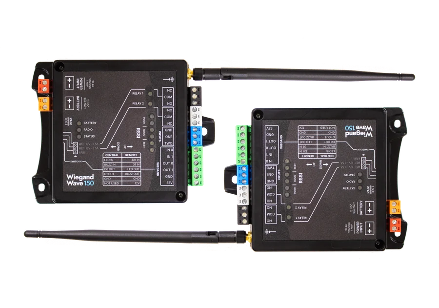
Two Wiegand Wave 150 units carrying one reader across a gap. This guide covers mounting, wiring, pairing and testing both units.
What you're installing
- Wiegand Wave 150 WW150Two of them. They work as a pair, so neither one can be set up on its own. Ordered together they are WW152.
What you need before you start
The units work as a pair and neither one can be configured alone, so have both in front of you.
- Two Wiegand Wave 150 units, with the antenna that came with each one
- A 15 to 24 VAC or VDC supply rated 2A for each unit
- A ⅛ inch flathead screwdriver for the terminal blocks
- The reader at one end and the access control panel at the other
Optional at each unit: a 12V sealed lead acid battery for backup power.
The Wiegand Wave 150 is not water resistant
Both units need an enclosure you supply if they are going anywhere weather reaches.
Keep the antenna outside any metal enclosure. A metal box around the unit confines the antenna and takes the link with it.
Which unit is Central and which is Remote
The two units are the same part. What makes one Central and the other Remote is DIP switch 4 and what you wire into it.
| Property | Central unit | Remote unit |
|---|---|---|
| Where it goes | At your access control panel, indoors | Out at the door or gate, with the reader |
| What it connects to | The panel's reader inputs | The reader, and the lock or gate operator |
| DIP switch 4 | DOWN | UP |
Both tables are printed on the face of every unit, and the full terminal reference is in the Central and Remote wiring guide.
Mounting both units
- Screw the antenna down tight before the unit goes on the wall, tight enough that it cannot swing in any position. An antenna that moves drops the link intermittently, which is far harder to find than one that never worked.
- Mount each unit high, dry, and with as clear a path to its partner as the property allows. Indoors, near an exterior wall or a window is better than the middle of a building.
- Keep at least 20cm between any antenna and a person. This is an FCC separation requirement.
Power
| Block | Takes |
|---|---|
| Red | 15 to 24 volts, AC or DC |
| Orange | A 12V sealed lead acid battery, and nothing else |
The status LED comes on once the red block has power. On the Remote unit the reader takes its 12V from the green block, so the reader powers up as soon as that is landed.
Wiring
Both units carry the same terminal blocks in the same colors. What changes is what you land on them.
Central unit
At the panel. DIP switch 4 down.
| Block | Terminals | Goes to |
|---|---|---|
| Green | 12V, Ground, Data 1, Data 0, LED (IN 1), Buzzer control (IN 0) | The panel's reader inputs |
| Blue | Input 2, Input 1, Ground | Door position or other contacts you want reported back |
| White | Normally closed, COM, Normally open | Auxiliary relay |
| Black | Normally closed, COM, Normally open | Relay |
Remote unit
At the door or gate. DIP switch 4 up.
| Block | Terminals | Goes to |
|---|---|---|
| Green | 12V, Ground, Data 1, Data 0, LED (IN 1), Buzzer control (IN 0) | The reader |
| Blue | Input 2, Input 1, Ground | Request to exit button, or a door contact |
| White | Normally closed, COM, Normally open | Auxiliary relay |
| Black | Normally closed, COM, Normally open | The lock, strike or gate operator |
The inputs and the relays cross over
A contact closed on one unit fires the matching relay on the other one. Wire each end to the panel and the door as though the two were joined by cable.
So a door position contact on the Remote unit closes Relay 1 at the Central unit, where the panel is watching. An approved read closes the panel's contact into the Central unit, which fires Relay 1 out at the Remote unit and opens the door.
The full terminal by terminal reference for both roles is in the Central and Remote wiring guide.
DIP switch settings
The bank sits on the side of the unit, beside the orange battery terminals.
| Switch | Up | Down |
|---|---|---|
| 1, Relay 1 | Dry | Wet |
| 2, Relay 2 | Dry | Wet |
| 3, pairing | Normal | Pairing mode |
| 4, unit role | Remote | Central |
A dry relay is a plain switch that opens and closes a circuit without supplying anything. A wet relay puts out 12VDC at up to 1.5A when it fires, so it can drive a device directly. Pick per relay, against how the lock is powered.
Pairing the two units
Do this on the bench before either unit goes on a wall. The units do not have to be near each other, but it is easier when they are.
- 1Power both units. 15 to 24 VAC or VDC into the red block on each one. Bench power is fine, and the units do not have to be near each other.
- 2Move every DIP switch up on both units. This is the known starting position, and the rest of the steps assume it.
- 3Hold the Pair/Test button on both units for about ten seconds. Let go when the six RSSI LEDs flash three times. That clears whatever either unit was paired to before.
- 4Set the roles on DIP switch 4. Switch 4 down on the unit going to the panel. Switch 4 up on the unit going out to the reader.
- 5Put both units into pairing mode on DIP switch 3. Switch 3 down on both. This is the switch the Endpoint does not have, so do not go looking for a power cycle here.
- 6Press Pair/Test on the Central unit. The RSSI LEDs count up until all six are lit on both units. That is the pair finished.
- 7Put DIP switch 3 back up on both units. Back to normal mode. Leave it there.
Once they are paired the two units talk every 30 seconds, and the RSSI LEDs light on each exchange. LEDs coming up on both units on that cycle is how you know the pair took.
What each LED means
The LEDs are the only readout on the unit, so they are what tells you where a fault is before anything comes off the wall.
| LED | In normal operation |
|---|---|
| RSSI | Six LEDs showing signal strength. They light on each exchange, which is every 30 seconds once a pair is up. |
| Radio | Blinks when the unit sends or receives. A blink on a card read is the link doing its job. |
| Status | Flashes every five seconds as a heartbeat, so a unit with power and firmware running is never dark. |
| Battery | Lit when the unit is running on the optional 12V sealed lead acid battery. |
| Relay 1 and Relay 2 | Each one lights while its relay is closed. |
A unit with no LEDs at all has no power, so start at the red block rather than at the radio.
Testing the link
- 1Press Pair/Test on either unit. The RSSI LEDs on both units strobe if the link is up.
- 2Put a reader on the Remote unit and swipe a fob. The reader should power up as soon as 12V and ground are landed. On the swipe, the RSSI LEDs light and the radio LED blinks once to say a message went out.
- 3Check the code at the panel. The Central unit should hand the panel a Wiegand code matching the fob you swiped.
- 4Check the relay. Wired to a panel, an approved read closes the relay on the Remote unit, which is what actually opens the door.
- 5Repeat it with both units mounted where they are staying. A link that tests clean on a bench and poorly on the wall is an antenna position problem, not a pairing problem.
| LEDs lit | What it means |
|---|---|
| 1 to 2 | Poor. An occasional 1 or 2 is fine, but a steady 1 or 2 is not a stable link. Review where the units and antennas are placed. |
| 3 to 4 | Good. |
| 5 or more | Best. |
Do not leave a job on a poor reading
Move an antenna, or move a unit, until the reading is good. A marginal link works on the day and fails in weather, and that becomes a call-out.
Unpairing
To break a pair, so a unit can be paired to a different one.
- 1Move every DIP switch up on both units.
- 2Hold the Pair/Test button until the LEDs on top of the unit flash three times, which takes about ten seconds.
The units do not need to be near each other for this, and it is the same hold that starts a fresh pair.
If it still isn't working
Aether RF product support takes calls from installers directly, so you don't need to go through your distributor first. If you're on site with the units in front of you, calling is fastest.
Weekdays, 8:30am to 5:30pm Arizona time. Send a support request instead.