
Point to Point installation guide
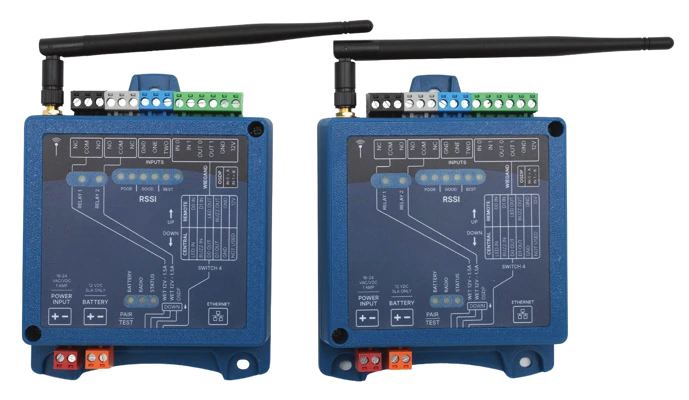
Two KNECT Endpoints, one at your access control panel and one out at the door or gate. This guide covers mounting, wiring, pairing and testing both units.
What you're installing
- KNECT Endpoint KEP-200Two of them. One at your access control panel, one out at the door or gate.
What you need before you start
In the box
- Two KNECT Endpoints (KEP-200), each with its antenna
- A transformer for each unit
You supply
- A small flat screwdriver for the terminal blocks
- An Ethernet drop at the Central unit, if you want the system on the Aether RF IoT portal
- A 12V sealed lead acid battery at either unit, if you want battery backup
A point to point system doesn't need the portal to work. Wire it, pair it, and it passes credentials whether or not it's ever connected. The Ethernet drop is what lets you check signal strength and pull logs later without driving out to the site.
Which unit is Central and which is Remote
The two Endpoints are the same hardware. What makes one Central and the other Remote is DIP switch 4 and what you wire into it.
Set this before you mount anything, because getting it backwards is the most common reason a link never comes up.
| Property | Central unit | Remote unit |
|---|---|---|
| Where it goes | At your access control panel, indoors | Out at the door or gate, with the reader |
| What it connects to | The panel's reader inputs | The reader, and the lock or gate operator |
| DIP switch 4 | DOWN | UP |
| Ethernet | Needed for the portal | Not used |
Mounting both units
Antenna placement decides whether the link holds, so it's worth more care than the rest of the install put together.
- Screw each antenna down tight before the unit goes on the wall, and point it straight up.
- Mount both units high, with as clear a path between them as the building allows.
- Indoors, get them near an exterior wall or a window on the side facing the other unit.
Neither unit is water resistant
A KNECT Endpoint mounted outdoors needs an enclosure you supply.
The antenna goes outside the enclosure, because a metal box around the antenna will confine the signal.
Power
15 to 24 VAC or VDC into the red block, on each unit.
Both units take their own power. There's no power over the radio link and nothing passes power to the far unit.
Wiring
Both units carry the same terminal blocks in the same colors. What changes is what you land on them.
Central unit
At the panel. DIP switch 4 down.
| Block | Terminals | Goes to |
|---|---|---|
| Green | 12V, Ground, Data 1, Data 0, LED (IN 1), Buzzer control (IN 0) | The panel's reader inputs |
| Blue | Input 2, Input 1, Ground | Door position or other contacts you want reported back |
| White | Normally closed, COM, Normally open | Auxiliary relay |
| Black | Normally closed, COM, Normally open | Relay |
Remote unit
At the door or gate. DIP switch 4 up.
| Block | Terminals | Goes to |
|---|---|---|
| Green | 12V, Ground, Data 1, Data 0, LED (IN 1), Buzzer control (IN 0) | The reader |
| Blue | Input 2, Input 1, Ground | Request to exit button, or a door contact |
| White | Normally closed, COM, Normally open | Auxiliary relay |
| Black | Normally closed, COM, Normally open | The lock, strike or gate operator |
The full terminal by terminal reference for both roles is in the Central and Remote wiring guide.
DIP switch settings
The switch bank is printed on the face of the unit.
| Switch | Up | Down |
|---|---|---|
| 4, unit role | Remote | Central |
The remaining switches set each relay for a wet or a dry contact, to match how the lock is powered. Set them against the legend printed beside the bank on the unit in front of you, because the numbering is not the same across every KNECT product.
Pairing the two units
Do this once both units have power. They don't have to be in their final positions yet, but it's easier to read the signal strength if they are.
- 1Power both units 15 to 24 VAC or VDC into the red block on each one.
- 2Set the roles on DIP switch 4 Switch 4 up on the unit going out to the door or gate. Switch 4 down on the unit at the panel.
- 3Power cycle both units Unplug each one for 30 to 60 seconds, then plug it back in. They read their role at startup, so the roles you just set don't take until they've restarted.
- 4Watch the Central unit's RSSI lights They come on once the Remote unit starts transmitting. If nothing lights up, the Remote unit either isn't powered or isn't set to Remote.
- 5Press Test/Pair on the Central unit The two units transmit back and forth six times. Let it run.
- 6Wait for the transmissions to stop That's the pair finished. The status LED then flashes once every five seconds. If it flashes twice, the pair didn't take, so power cycle both units and run it again.
Testing the link
Press and release Test/Pair on either unit. It sends a test transmission, and any paired unit in range answers with its signal strength on the RSSI lights. The unit you pressed beeps when the test packet gets through.
Do this before you close up the enclosures. Moving an antenna a foot is cheap while you're standing there and expensive once you've packed the van.
Reading the RSSI lights
| Lights | Signal |
|---|---|
| 1 to 2 | Poor. An occasional 1 or 2 is fine, but a steady 1 or 2 is not a stable link. Review where the units and antennas are placed. |
| 3 to 4 | Good. |
| 5 or more | Best. |
Unpairing and factory reset
Do this when you're moving a unit to a different system, or when a pair won't take and you want both units back to a known state.
- 1Move every DIP switch to the up position on both units.
- 2Hold the green Test/Pair button on both units until the Radio and Status LEDs go solid and stay solid for five seconds.
If it still isn't working
Aether RF product support takes calls from installers directly, so you don't need to go through your distributor first. If you're on site with the units in front of you, calling is fastest.
Weekdays, 8:30am to 5:30pm Arizona time. Send a support request instead.