
Central and Remote
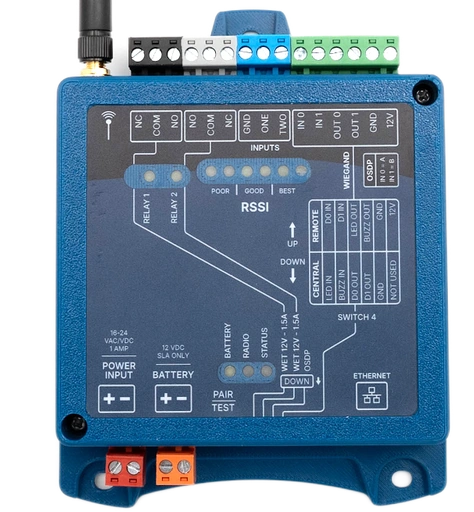
The two units in a pair are the same part. Which one is the Central and which is the Remote comes down to what you land on it and where DIP switch 4 sits, and both wiring tables are printed on the face of every unit.
This is the full terminal reference for both roles. It covers the KNECT Endpoint and the Wiegand Wave 150, which print the same wiring table.
Which unit is which
The unit at your access control panel is the Central. The unit out at the door or gate is the Remote.
| Property | Central unit | Remote unit |
|---|---|---|
| Where it goes | At your access control panel, indoors | Out at the door or gate, with the reader |
| What it connects to | The panel's reader inputs | The reader, and the lock or gate operator |
| DIP switch 4 | DOWN | UP |
Both units read their role when they start up, so a switch moved on a powered unit does nothing until you power cycle it.
The table printed on the unit
This is the table on the face of the device, reproduced exactly. The KNECT Endpoint and the Wiegand Wave 150 print it identically, so a pair of either reads the same way.
| Central | Remote |
|---|---|
| LED IN | D0 IN |
| BUZZ IN | D1 IN |
| D0 OUT | LED OUT |
| D1 OUT | BUZZ OUT |
| GND | GND |
| Not used | 12V |
Read the two columns as a pair of lists rather than as a mapping onto the terminal block above them. The block is printed in a different order from this table, so match a row to its terminal by name and not by position.
Central unit, terminal by terminal
At the panel, DIP switch 4 down.
| Block | Terminals | Goes to |
|---|---|---|
| Green | 12V, Ground, Data 1, Data 0, LED (IN 1), Buzzer control (IN 0) | The panel's reader inputs |
| Blue | Input 2, Input 1, Ground | Door position or other contacts you want reported back |
| White | Normally closed, COM, Normally open | Auxiliary relay |
| Black | Normally closed, COM, Normally open | Relay |
Remote unit, terminal by terminal
At the door or gate, DIP switch 4 up.
| Block | Terminals | Goes to |
|---|---|---|
| Green | 12V, Ground, Data 1, Data 0, LED (IN 1), Buzzer control (IN 0) | The reader |
| Blue | Input 2, Input 1, Ground | Request to exit button, or a door contact |
| White | Normally closed, COM, Normally open | Auxiliary relay |
| Black | Normally closed, COM, Normally open | The lock, strike or gate operator |
The rest of the board
The terminal blocks along the top edge of the board, left to right.
| Block | Terminals | On |
|---|---|---|
| Relay 1 | NC, COM, NO | Both devices |
| Relay 2 | NC, COM, NO | Both devices |
| Inputs | GND, ONE, TWO | Both devices |
| Wiegand | IN 0, IN 1, OUT 0, OUT 1, GND, 12V | Both devices |
| OSDP | IN 0 pairs to A, IN 1 pairs to B | KNECT Endpoint only |
The Endpoint also carries an Ethernet port, which the Wiegand Wave 150 does not. That port is what puts a system on the Aether RF IoT portal, and it goes on the Central unit. A pair passes credentials whether or not it is ever connected.
DIP switches
Four switches, marked SWITCH 4 on the face with the up and down directions shown beside the bank.
| Switch | Up | Down |
|---|---|---|
| 1, Relay 1 contact | Dry | Wet, 12V at 1.5A |
| 2, Relay 2 contact | Dry | Wet, 12V at 1.5A |
| 4, unit role | Remote | Central |
Switch 3 is not the same on both products. On the Wiegand Wave 150 it is the pairing switch, normal up and pairing down. On the KNECT Endpoint it is marked OSDP. Set switch 3 against the legend printed beside the bank on the unit in front of you.
If the roles are set wrong
Two units set to the same role will not pair, and neither of them is faulty.
What you will see
The Central unit's RSSI LEDs stay dark, because they only come up once the Remote unit starts transmitting. After a pairing attempt the status LED flashes twice every five seconds instead of once.
What to do
Set switch 4 down on the unit at the panel and up on the unit at the door or gate. Power cycle both for 30 to 60 seconds, because each one reads its role at startup. Then pair them again.
Nothing about this is a hardware fault and neither unit needs returning. If the pair still will not come up after a power cycle, the troubleshooting guide narrows it down to the antenna, the wiring or the panel.
If it still isn't working
Aether RF product support takes calls from installers directly, so you don't need to go through your distributor first. If you're on site with the units in front of you, calling is fastest.
Weekdays, 8:30am to 5:30pm Arizona time. Send a support request instead.